Introduction
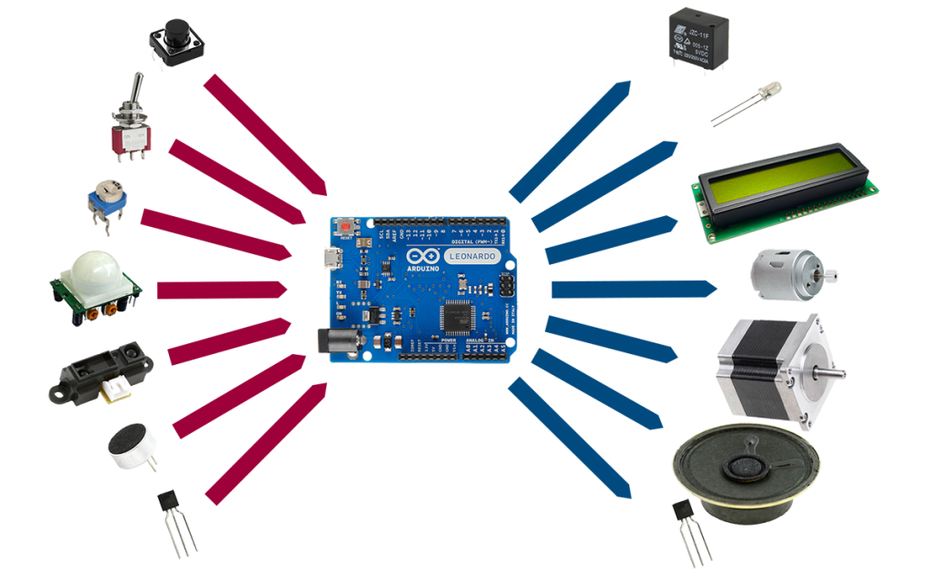
A microcontroller (uC) is a computing device. Its main job is to perform computations... it takes some data from its memory, manipulates them, and then stores them back to memory. But having data in a uC's RAM doesn't do much good. In order to make use of that information, we have to be able to take it out of the uC and realize it in some way. To do that, a uC has outputs that can transfer out bits of information to devices that can display it, make sound or light, cause something to move, etc.
In many occasions though, we don't have our data ready in advance. Some times, we want to transfer data in the uC as they become available. Other times, we want to let the user interact with the uC, or we want to sense different aspects of the environment around us. For those reasons, a uC also has inputs that let it take in information.
We are given access to the inputs and outputs (IO) of a uC through the pins of its IC package. The circuit behind each IO pin is built such that the user can configure that pin as either input or output.
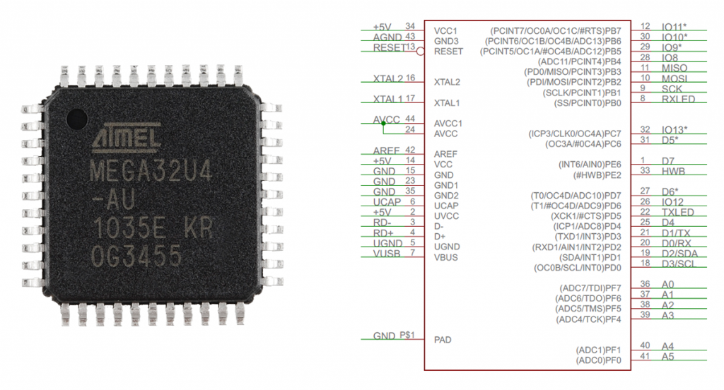
A uC has many capabilities that require many pins to accommodate them all. Often that number of pins is more than what a specific IC package can carry. To solve that problem, some pins are being multiplexed. This means that different circuits are guided to the same pin. Then, depending on the operation we are carrying out, one of those circuits is connected to the pin at any time. For example, in the ATMEGA32U4 we see that pin 21 can be used either as an IO pin (D1), or as a serial output line (TX).
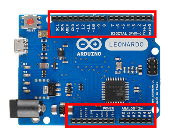
On an Arduino board, the pins of the uC are broken out and connected to female pin headers so they are more accessible. They are organized into groups and are given new names with which they are going to be referenced in the code.
Analog Inputs

An analog signal describes a physical variable that varies continuously with another variable (often time). Examples of analog signals are the intensity of light of an LED as its current increases, the current going through a resistor as we vary the voltage, or the temperature in a room as the time passes.
An analog signal can take on infinite values. Unfortunately a uC cannot represent an infinite number of values. So what we do when we want to sample an analog signal is perform an Analog to Digital Conversion (ADC). This basically means that we pick specific values in a region and then we use a series of bits to represent those values only. Any intermediate values are truncated to the closest representable value.
Let's say we have an analog sensor that gives an output in the region of \(0-5 V\) and an A-to-D converter with a \(10bit\) resolution. This means that we can represent \(2^{10}\) or \(1024\) values. The procedure goes as follows: We divide the \(0-5 V\) region into \(2^{10}\) sub-regions of \(4.88 mV\) width, and assign to each one a bit combination. So we get: \([0, 4.88mV) \rightarrow 0000000000,\) \([4.88mV, 9.76mV) \rightarrow 0000000001,\) \([9.76mV, 14.64mV) \rightarrow 0000000010...\) and we keep adding ones \((1)\) up to \([4.995V, 5V] \rightarrow 1111111111\).
Now, let's say we sample the sensor's output and the value we get is \(2.932 V\). This value falls into the \([2.930V, 2.935V)\) sub-region. So the bit combination we get back from the A-to-D converter is \(1001011000\), which is the number \(600\) in decimal. (If interested in how to convert a binary number to a decimal, read here.)
The analog pins on an Arduino board are named Ax, where x is a number. We use these names to reference the analog pins in the code. We can read a value from an analog input pin with the analogRead function. This function requires a pin number as an argument, and returns an int value (the value read from the A-to-D converter).
Analog Outputs

An analog output is produced by a process called Digital to Analog Conversion (DAC). A D-to-A converter takes in a binary number and outputs an analog signal (a constant value, e.g. \(0100011111 \rightarrow 1.4V\)). Unfortunately, unlike reading analog inputs (ADC), writing analog outputs (DAC) isn't something that all uC support. If that is the case with your own uC then you will need to buy a DAC module.
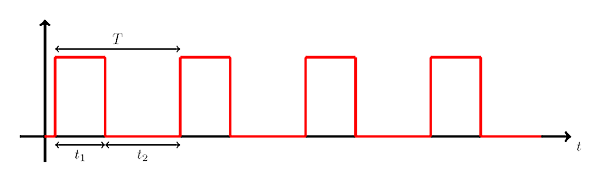
On the other hand, a common feature on many uC is the Pulse Width Modulation (PWM) capability. A PWM(odulated) signal is a square wave (shown above), a.k.a. pulse train. It is a periodic signal, so it has a frequency \(f\), measured in either \(kHz\) or \(MHz\), and a period \(T=1/f\), measured in either \(ms\) or \(us\). A pulse in a PWM signal has an on time and an off time. The on time \(t_1\) is the time that the pulse stays HIGH. The off time \(t_2=T-t_1\) is the time that the pulse stays LOW. The last but not least parameter that describes a PWM signal is the duty cycle which defines the percentage of time that one pulse stays on, \(\frac{100t_1}{T}\).
The interesting thing about the duty cycle is that varying it from \(0\) to \(100\), it changes the average value of the PWM signal.
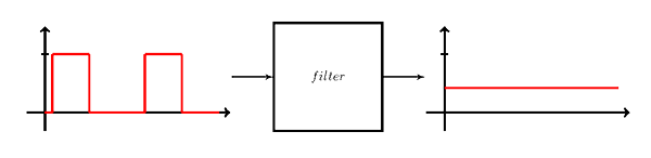
A PWM signal is not an analog signal, but we can make one out of it. We can use a special circuit to smooth the PWM signal out and make its average value appear (but this is a subject for a whole other tutorial). Also, this is sort of where the analogWrite function got its name from.
The PWM pins on an Arduino board are designated with a ~ symbol. In the code, we use the analogWrite function to output a PWM signal. Its arguments are the pin number to which to write, and the duty cycle defined here as a number between 0 and 255.
Digital Inputs

A digital signal, unlike an analog signal, cannot take on infinite values. The digital signals of interest to us take only on two values referred to as 0 and 1, or LOW and HIGH, respectively. Examples of digital signals are the on-off state of an oven, the movement-no movement state of a PIR sensor, or the pressed-not pressed state of a push button.
We declare an IO pin as input or output through the use of the pinMode function. This function takes two arguments. A pin number, and one of the following constants to declare the pin's mode: INPUT, OUTPUT, or INPUT_PULLUP.

A very simple form of input component is a switch. A switch can be either open or closed. It has two leads, one of which we connect to a point of reference (GND or VCC), and the other to an input pin on our uC. When the switch is closed, the input pin is connected to the point of reference and we read an appropriate value. But when the switch is open, the input pin is left floating and is picking up electrical noise from the environment. As a result reading from the input pin when the switch is open gets us back a random value. To solve this problem, we make use of a resistor that we connect to another point of reference and the input pin. Now, when the switch is open, the input pin connects to a point of reference and we read a known value. A resistor, when used in this manner, is called either pull-up or pull-down, because it pulls the input pin either up to VCC or down to GND.
Arduino boards include internal pull-up resistors that we can make use of, if necessary. In that case, we can actually connect a switch alone on an input pin. We just have to remember to enable the pin's pull-up resistor in the code.
We can read a digital input with the digitalRead function. It takes a pin number as argument, and returns HIGH or LOW.
Digital Outputs
Finally, we get to digital outputs. Not much is left to say. In the code, we declare an IO pin as output with the pinMode function, and we write to a digital output with the digitalWrite function. The digitalWrite function takes two arguments. One is a pin number and the other is the state to write to the pin, HIGH or LOW.
Conclusion
Inputs or outputs, analog or digital, signals of any form... now you know enough to interface them all. Now you have the power. I know these are a lot to take in, but hang in there. The possibilities that open up just with those things alone are countless. Next time, we'll see already some applications! ;)
Images of specific components are courtesy of arduino.cc, sparkfun.com, and adafruit.com. Others are in the public domain.
Images are CC BY-NC-SA 3.0.