AlarmClock Tutorial from codebender on Vimeo.
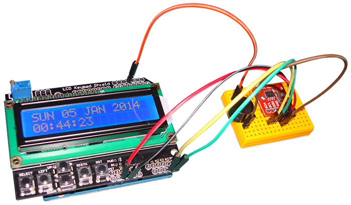
This is a tutorial on how to build an alarm clock. This alarm clock will have its basis on an LCD Keypad shield and a DS1307 Real Time Clock module.
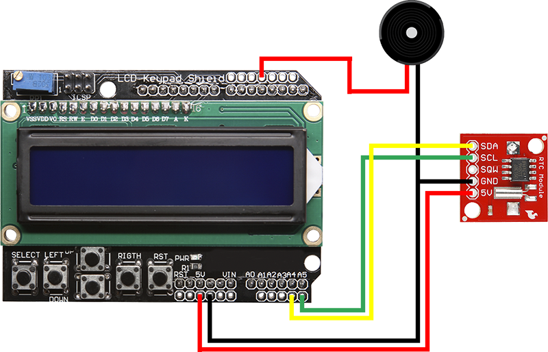
So... an alarm clock. This is the schematic.
Now, what do we want from a alarm clock? Well, we want it to show date and time, that's what the RTC module offers. Then we want an alarm, and the ability to turn the alarm on and off, set the alarm time, see the alarm time, and have a snooze function. That's basically it.
So, we want a device that has to process and maintain information, as well as handle its hardware. It has to do quite a few things and manage to coordinate them in real time.
I tried to start from here and build the clock. The steps I had to go through were to get the data from the RTC module, display them on the LCD screen, and look for user input for which I'd like to have an immediate response. But we can't just throw these inside a loop and get done. There are hardware restrictions, like the refresh rate of the LCD screen. There are also logical considerations, like that there is no need to update time more frequent than once per second. Also, we can't pause the Arduino and wait for a second, since we expect user input at any time. And then try to add menus and let the user navigate, and blah blah blah... you get the idea. Things can get really complicated very quickly, and that's when you start doing all sorts of hacks and tricks to make the clock appear functional. I did that myself as an experiment and the result was at the very least poor.
So, what do we do? We have to stop, before we put our hands on the keyboard, and think about the problem at a higher level. We have to somehow organize things, view the problem as a system, anticipate and design appropriately.
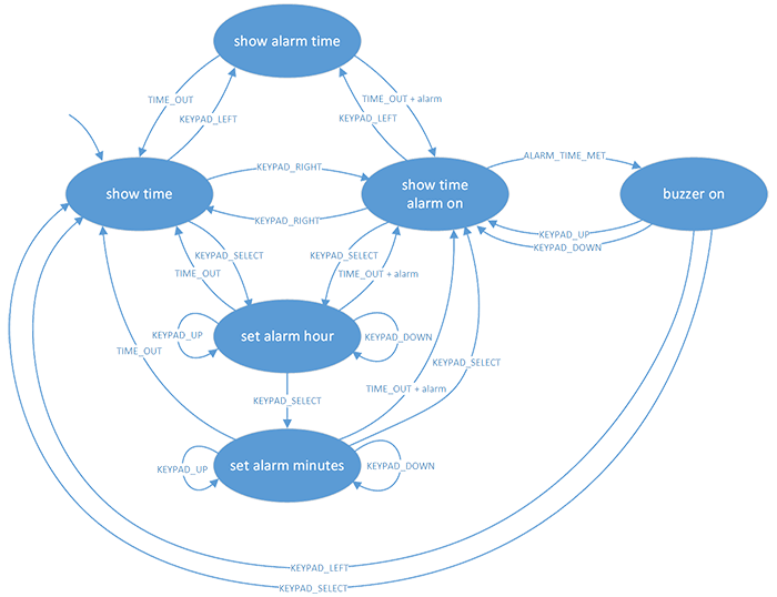
And this is the result of such a process... a state diagram.
Our clock has to do various things. We'll try to divide those into categories that we will call states. When the clock is in a state, it does something specific... its operation is well defined. And then we expect things to happen that will change the state of the system and cause it to do something different.
To sum up, we have a system that can be in different states, and then we have events that make the system transition to another state.
So, we sit down, we think about the problem, and we come up with something like the diagram above. Let's look at what this diagram says.
We start at the show time state. Here, the date and time appear on the screen. By pressing the RIGHT button, we change state, the alarm turns on and also an ALARM indication appears on the screen. By pressing the RIGHT button again, we turn off the alarm and move back to the show time state. From either the show time or the show time alarm on state, by pressing the LEFT button, we move on to the show alarm time state whose operation is self explanatory. After 3 seconds, a time out occurs, and we go back to the state we came from. From the same two states, by pressing the SELECT button, we transfer to the set alarm hours state where we get to set the hours part of the alarm time. If we don't press any of the UP or DOWN buttons within 5 seconds, a time out happens and the process cancels. If we press the SELECT button, we move on to set the minutes part of the alarm time. Again, after 5 seconds of inactivity the process cancels. If we hit SELECT, the alarm time gets updated, the alarm turns on, and we go to the show time alarm on state. From that state, if the alarm time has come, we transition to the buzzer on state where a buzzer starts ringing. From there, if we hit either UP or DOWN, the buzzer turns off, 10 minutes are added to the alarm time, and we move back to the show time alarm on state. On the other hand, if we hit SELECT or LEFT, the buzzer goes off along with the alarm setting, and we transfer back to the show time state. Any button, at any state, that's not mentioned, has no effect on the states of the system.
And we are done. Now, we put this diagram beside us and start coding.
There are two main parts in this implementation. The loop function where the current state is recognized and the proper function is called to handle whatever needs to be done, and then we check for button presses and if a valid button is pressed, a state transition is performed. The second part is the transition function that gets an event and performs the appropriate state transition along with any necessary variable updates. This is the control part of the system. The rest of the functions handle the hardware. You can watch an example of the alarm's performance in the video.
So, this is it. We start from a diagram and we end up with an implementation. But the very best part of this approach, and the beauty of it, is that the system is totally expandable with minor or zero code changes. You can add any features you want to the current design, and you won't have to worry a bit about what the rest of the implementation does.
Finally, there is one more issue that is out of the specification. This is the setting of the current date and time. If you need to set the date and time on the RTC module, uncomment line 96 in the code, upload the example to your Arduino, then comment the line back, and upload the code again. Now, the time is saved on the RTC module that is backed with a battery, and even if the power goes down and later the Arduino resets, you won't have to set the time again... the RTC module will keep running.
RTCRAMRead example
One last bonus note. The code makes use of the RTClib library from Jeelab. This library doesn't support a neat feature there is on the DS1307 RTC module. This is the 56 byte RAM. So next, follows an example that demonstrates how to interface this RAM space. Read the example's description for more details.
That's all folks. We hope you enjoy this project, and if you have any comments or suggestions you can contact us at girder [at] codebender [dot] cc
Sounds are from freesound.org. Schematics were based on Fritzing.


