Power Cell LiPo Charger - Booster Tutorial from codebender on Vimeo.
This is a tutorial on the Power Cell LiPo Charger/Booster from Sparkfun. This module is used with the prevailing choice of LiPo batteries and is comprised of two separate circuits. One of those is a Boost Converter that its purpose is to supply a fixed and stable output voltage for a range of input voltages. The other circuit is a LiPo Charger that can charge a single cell LiPo battery either from an external 5V source or a USB port.
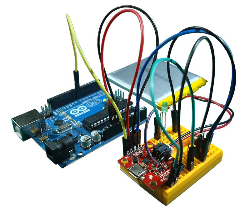
The module has some extra features. One feature is the solder jumpers next to the JST connector that can pick a 3.3V or 5V output for the boost converter. Then, there are the EN and PS pins that are tied to the operation of the boost converter. The EN pin, when driven LOW, disables the boost converter, and so the VCC output pin doesn't supply any power. The purpose of the PS pin is somewhat more involved, but basically when driven LOW, it makes the boost converter more efficient and consequently consumes less power. Lastly, there is a status LED controlled by the charger and it goes off when the battery is charged.
The Power Cell module was built both with the boost converter and the charger on board for one specific reason... so, you don't to take the battery away from your project, plug it in your charger, and then put it back again, every time the battery needs charging. Now, you can just plug your USB cable in and wait for the battery to charge. But as long as your project is connected to the VCC and GND pins, it's going to consume energy. This means that the battery will be supplying power while is charging, and the whole process will take longer to finish (when the charging process alone normally takes quite some time). So, with the project connected, the battery might take forever to charge.
So, if you have built your project and you've placed it inside an enclosure, ideally you'd want to just plug the USB cable in, let the battery charge as quickly as possible, and then have an indication to let you know that the process is finished. For these reasons, we will introduce 2 hacks to the current design of the Power Cell module. The first hack will drive the EN pin LOW when we plug a USB cable in, cutting off that way the rest of the project and letting the battery charge alone. The second hack will drive an LED that will light up when the battery is charged (this will only work with the MCP73831).
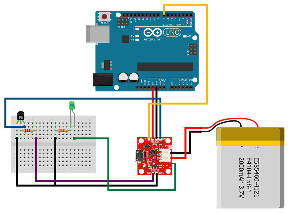
Let's begin... this is the schematic of the finished circuit.
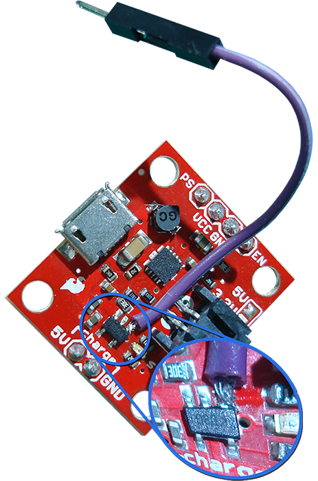
We'll need to do some soldering on the Power Cell PCB. Take a wire and solder its one end on pin 1 of the charger IC, like in the figure.
The rest of the components are a 3 mm green LED, a 330 Ohm resistor, a 2.2 kOhm resistor, and a generic NPN BJT transistor. Now... place the BJT on the breadboard. Connect one end of the 2K2 resistor to the base of the BJT (lead 2) and the other end of the resistor to a nearby column. Connect the 5V pin of the charge input to the other end of the 2K2 resistor. Connect the GND pin of the charge input to the emitter of the BJT (lead 1). Connect the collector of the BJT (lead 3) to the EN pin. Place the LED on the breadboard. Connect one end of the 330R resistor to the negative lead of the LED and the other end to a nearby column. Connect the other end of the 330R resistor to ground. Connect the other end of the wire you soldered earlier on the PCB, to the positive lead of the LED. Connect the VCC and GND pins of the Power Cell to the 5V and GND pins on the Arduino, respectively. Connect the PS pin to PIN7 on the Arduino. And finally connect the battery to the JST connector of the Power Cell.
When we connect the battery, the status LED on the Arduino lights up, and later when we plug the USB cable in, it turns off... so the Arduino draws no power, the battery is charging, and when the charging ends, the green LED lights up and we can take the USB cable away.
That's all but one thing about the operation of the Power Cell module. This one thing is the PS pin that we will interface with the Arduino. The PS (Power Save) pin is driven HIGH with a pullup resistor on the PCB. In this configuration, the boost converter operates in normal mode where it does some work to provide a reliable output voltage. But that work doesn't come free, it consumes energy from the battery. In situations where our project doesn't need that much power, we can drive the PS pin LOW and put the boost converter in power save mode where it stops and only kicks in when the output voltage tries to fall below a nominal value.
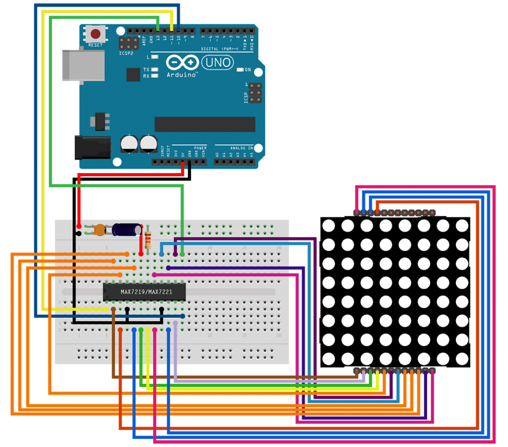
So, let's build an example application and see how we could make use of the PS pin. We will simulate a high load situation with an LED Matrix. Operating an LED Matrix doesn't really need that much power, but if we try to build a bigger display with, say, a dozen matrices, then that will demand a considerable amount of power. The LED Matrix will be a bicolor red/green common cathode one, and from the two colors we will be using the green one. We will interface the LED Matrix with a MAX7219 driver, and then we will communicate with the driver through the SPI bus. We will also use a push button to turn the system on and off, and accordingly put the boost converter in power save mode.
This is the schematic for the LED Matrix part of the system. It's pretty big, so take your time and make sure to do the right connections. The ceramic capacitor is 100 nF. The electrolytic capacitor is 10 uF (pay attention to its polarity). The resistor is 12 KOhms.
This is the schematic of the push button. It has a pullup resistor and an RC filter. The output of the RC filter connects to interrupt INT0 on the Arduino.
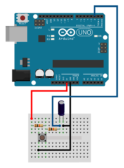
Normally the output of the RC filter would connect to a schmitt trigger inverter to provide a clean output that would drive the interrupt pin, but since I didn't have such a part, I had to improvise. I tested and picked some values for the components and then I did a software debouncing of the switch. The result I got isn't perfect, it works most of the time, but if a button press doesn't do anything permanent to your project (such that multiple presses would mess things up), you can use this approach with no worries. The two resistors are 10 KOhms and the capacitor is 0.1 uF.
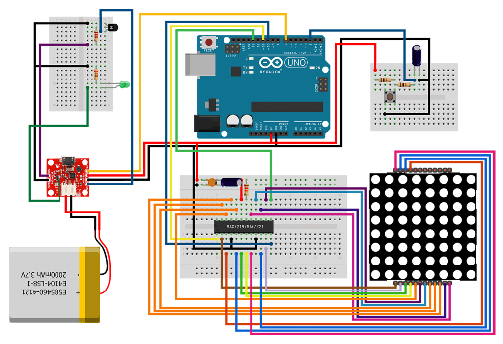
This should be the final project.
Now let's look at the code. For details on what the example does, you can read the comments.
The one thing I want to emphasize is what happens with the PS pin of the Power Cell when the button is pressed. On a press of the button, an interrupt is generated and the statusUpdate function is executed. There, the status and done flags are updated, and when the program flow returns to the loop function, the LED driver will go either in normal or shutdown mode, and the boost converter will go either in normal or power save mode.
That's all folks. We hope you enjoy this project, and if you have any comments or suggestions you can contact us at girder [at] codebender [dot] cc
Sounds are from freesound.org. Schematics were based on Fritzing.
Article Tags
Categories
- Advanced Tutorials [10]
- Basic Tutorials [52]
- Developers say [31]
- Events [15]
- Features Recap [7]
- Fun Times [7]
- News [3]
- Tech Stuff [93]
Archives
Tags
- 1sheeld 1
- 2015 1
- 7 segment 1
- 74hc4067 1
- 74HC595 1
- A7corsair 1
- academy 1
- ace editor 1
- acquisition 1
- actuator 1
- adafruit 7
- adc 1
- adding files 1
- additions 1
- airboard 1
- alarm 1
- alert 1
- altimeter 1
- analog 2
- analog read 1
- analogRead 1
- anode 1
- app update 1
- Arduboy 1
- arduino 72
- Arduino Day 1
- arduino tone 1
- ArduinoD16 1
- Assetic 1
- async 2
- august 1
- automation 1
- aws 4
- awscli 1
- back end 1
- backup 1
- Badgerhack 1
- Badgerstick 2
- barometric pressure 1
- battery 2
- baud rate 2
- benefits 1
- blink 2
- blynk 1
- bmp280 1
- board 9
- boards 1
- boost 2
- boto 1
- bounce 1
- breadboard 1
- Brussels 1
- button 6
- button switch 1
- buzzer 2
- c++ 1
- card 1
- casperjs 1
- cathode 1
- celebration 1
- cell 1
- ch340 1
- ch340g 4
- ch341 1
- ch341g 1
- ch34x 1
- chai 1
- charge 1
- charger 1
- checksum 1
- christmas 2
- chrome 1
- chrome app 1
- chromebook 1
- chromeos 1
- circuit playground 1
- click 1
- clock 1
- closures 2
- code review 1
- codebender 127
- coding 2
- collaboration 1
- comments 1
- community 1
- compiler 3
- control 2
- converter 2
- crowdsource 1
- current 1
- curve 1
- dac 1
- data 1
- datapoints 1
- date 1
- day 1
- debounce 1
- debouncing 1
- demultiplexer 1
- dependency injection 1
- description 1
- design 1
- designer 1
- dev 2
- developer 10
- developers 1
- developers say 3
- devops 1
- DHT-11 1
- digital 2
- diode 1
- display 1
- disqus 1
- distance 1
- diving 1
- doctrine 1
- dome 1
- door 1
- driver 1
- drivers 6
- ds1307 1
- ds18b20 1
- editor 3
- education 1
- el capitan 1
- electronics 1
- emic2 1
- escape 1
- europe 1
- event 5
- events 1
- examples 2
- facebook 1
- fade 3
- fakedrake 2
- fast 1
- feature 3
- features 4
- features recap 6
- file 1
- finder 1
- fio 1
- firefox 1
- fitting 1
- flex resistor 1
- flex sensor 1
- flora 2
- FM 1
- FM Radio 1
- force 1
- FOSDEM 1
- fsm 1
- fuel 1
- fun 1
- fun times 3
- games 1
- gaming 1
- gas sensor 1
- gauge 1
- gemma 1
- Genuino Day 1
- GenuinoD16 1
- github 1
- go kart 1
- GP2Y0A41SK0F 1
- group 1
- guzzle 1
- hackathon 1
- HC-SR04 1
- HDT-22 1
- hiring 1
- homepage 1
- http client 1
- Humidity 3
- hummingbirdduo 1
- hygrometer 1
- i2c 1
- IDE 1
- include 1
- infrared 3
- input 3
- install 1
- installer 1
- interaction 1
- interrupt 1
- ion 1
- iOS 1
- IoT 1
- ir 2
- irranger 1
- isp 1
- javascript 3
- job 1
- july 1
- karma 1
- kext 1
- keypad 2
- kit 1
- kocoafab 1
- l293d 1
- L298 1
- landing page 1
- lcd 2
- LDR 1
- learning 1
- led 9
- Let's Start Coding 1
- libraries 4
- library 5
- lifuelgauge 1
- light 2
- lightup 1
- lipo 2
- list 1
- lithium 2
- littleBits 1
- load 1
- logging data 1
- LoRa 1
- LoRaWAN 1
- lowpowerlab 1
- lux 1
- mac 1
- Mac installer 1
- mac osx 1
- machine 1
- MacOSX 1
- magnetic 1
- Makeblock 1
- maker 1
- Maker Board 1
- maker faire rome 2015 1
- makercon 2
- makerfaire 4
- makers 1
- makey 1
- makezine 1
- map function 1
- marsone 1
- matlab 1
- matrix 1
- max7219 1
- max7221 1
- mCore 1
- ME Orion 1
- mega 1
- message 1
- message queue 1
- messaging 1
- metaprogramming 1
- microcontroller 1
- mocha 1
- model 1
- module 2
- moteino 1
- motor 2
- motor driver 2
- MQ gas 1
- multiple sessions 1
- multiplexer 1
- mux 1
- neomatrix 1
- neopixel 4
- new 8
- New board 9
- new boards 1
- new editor 1
- new feature 4
- new features 5
- new homepage 1
- new members 1
- new offices 1
- new plug in 1
- new stuff 4
- new year 1
- news 3
- node.js 1
- npn 1
- NSIS 1
- on boarding 1
- online IDE 1
- open 1
- opsworks 1
- option 1
- OrangeBoard 1
- OrangeBoard BLE 1
- ornament 1
- osx 1
- output 3
- P2N2222A 1
- PackageMaker 1
- page loader 1
- paintball 2
- pairing 1
- parameters 1
- parity 1
- partner 1
- partnership 1
- peer review 1
- personal libraries 1
- photocell 1
- photoresistor 1
- php 2
- phpunit 1
- piezo 1
- pioneer 1
- pitch 1
- plug in 3
- plugin 3
- polarity 1
- pole 1
- polymer 1
- position 2
- pot 1
- potentiometer 2
- power 2
- pro trinket 2
- process 1
- programming 2
- project view 1
- projects 1
- promicro 1
- protocol 2
- pull 1
- push 1
- pwm 3
- pytest 1
- python 4
- qmetric 1
- queues 1
- Radio 1
- ram 1
- range 1
- ranger 1
- RDS 2
- real 1
- receiver 1
- remote 1
- resistor 2
- rfid 2
- rgb 2
- ring 1
- robot 1
- room 1
- rotation 1
- rqbbitmq 1
- rtc 1
- Safari 2
- saucelabs 1
- scroll 1
- scrolling 1
- sd 1
- search 2
- seeed studio 2
- Seeeduino Mega 1
- Seeeduino Stalker 1
- segment display 1
- selenium 2
- sensor 12
- serial monitor 2
- servo 1
- seven segment 1
- shake switch 1
- sharp 2
- sharpirlib 1
- shield 2
- shift register 1
- si4703 1
- signal 2
- signing 1
- sinon 1
- sketch 1
- soc 1
- soil 1
- sort 1
- sorting 1
- sound 1
- sparkfun 3
- sparki 1
- speaker 2
- speech 1
- speed 1
- sshfs 1
- state 1
- STEM 1
- strip 2
- stuff 1
- switch 2
- symfony 3
- symfony2 4
- tag 1
- TEA5767 1
- tech 3
- tech stuff 1
- technical 2
- temperature 5
- templates 1
- teslakit 1
- testing 3
- tests 1
- text 1
- The AirBoard 1
- The Things Network 1
- The Things Uno 1
- TheAirbord 1
- thermistor 1
- threshold 1
- throw 1
- time 2
- tiny 1
- tiny circuits 1
- tinyscreen 1
- tmp36 1
- transistor 1
- transition 1
- tree 1
- trinket 2
- tsl2561 1
- tutorail 1
- tutorial 54
- tutorials 1
- type systems 1
- uart 2
- Ultrasonic 1
- unit tests 1
- update 5
- updates 4
- usb 1
- variable 1
- variable resistor 2
- vendor 1
- vibration 1
- voice 1
- voice commands 1
- voice module 1
- voltage 1
- volume 1
- walkthrough 1
- water flow 1
- water level 1
- wearable 1
- websockets 1
- wicked device 1
- wiegand 1
- wifi 1
- wildfire 1
- windows 2
- windows drivers 1
- wire 1
- wireless 1
- wishes 2
- wizfi210 1
- xmas 1
- yosemite 1