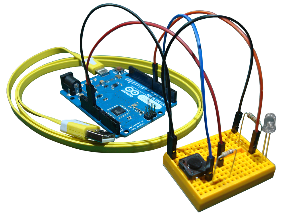
Here we are. The time has come to build our first projects. We'll meet the components in our disposal, figure out how to connect them, and then all we have to do is code. Code. Code... Code something useful that can make our everyday lives easier, or perhaps something fun that can entertain us. There is no stopping you from building anything... from the silliest children's toy to the next spaceship that will travel to Mars!
Arduino Code
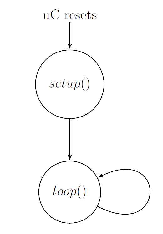
A basic Arduino program has the structure shown above. It consists of two functions, setup and loop. setup() is executed once, when the operation of the uC starts. loop() is called after the setup function has finished and is repeated indefinitely. This means that the code inside the loop function repeats again and again until the power goes down or the uC is reset.
Normally, inside setup we make the initial configuration of the uC and any libraries we may be using. Then, in the loop function we write the main code we want being executed over and over again, checking conditions and taking actions.
C++ is the language on which we will be writing code. I am going to assume that you have a basic familiarity with C or C++ programs. But even if you don't, don't be alarmed. There are tons of tutorials on the Internet. For reference, you can start from learn-c.org or learncpp.com. From my side, I will do my best to keep the examples simple, so you can follow along and figure out the details on the go.
Include a library: #include
Declare a constant: const int OUTPUT_PIN = 7;
Declare a variable: int data = 124;
Declare an array: char buffer[100];
Add a comment: // This is a comment
If structure: if ( data == 4 ) { ... }
While structure: while ( idx >= 0 ) { ... }
For structure: for ( int i=0; i<10; ++i ) { ... }
Define a function: void myFunction(int value) { ... }
Call a function: myFunction(data);
Breadboard
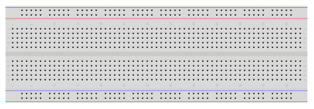
Before we move on with examining electronic components, we have to get introduced to the single most useful tool in our workbench that will be present in all of our projects. This is the breadboard. The breadboard will be the basis for our circuits. We will place the various components in the holes and then use extra wires to make the interconnections.
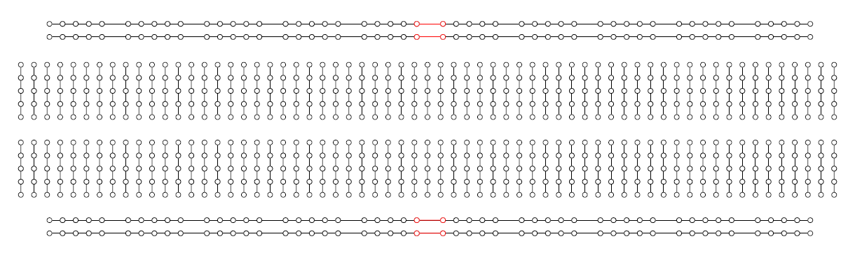
From inside, the breadboard has the structure shown above.
The inner holes are connected together vertically. So, a group (column) of 5 holes in the breadboard represents a node in the circuit. We place the leads of a component in different columns, and connect the leads of different components together with wires. The holes in the middle are not connected together. These holes have a special purpose. This is where we place ICs, so that two opposite pins are not short-circuited.
The outer holes are connected together horizontally. These interconnected holes form the power lines. This is where we bring the \(5V\) and \(GND\) voltage references. From there we take those voltages with wires to the components. Attention must be payed, since some breadboards break these power lines in the middle (red parts shown in the figure). In that case, left and right sides are created on the power lines and are not connected together.
LEDs
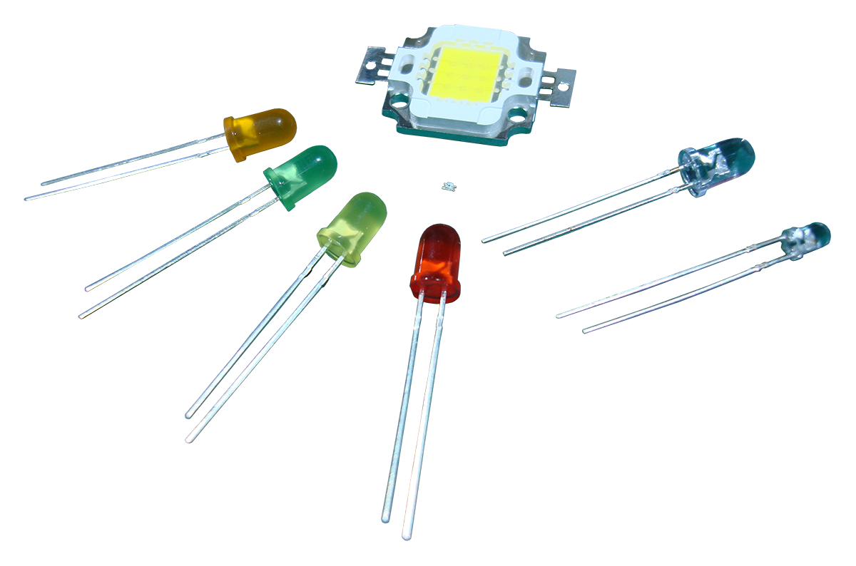
The first component we will see is the Light Emitting Diode (LED). LEDs are devices that when you run a current through them, they emit light. They can emit light of different frequencies, so we can encounter LEDs of a number of colors. They come in different forms and sizes. Common LEDs being used widely are the 5 mm round ones (shown to the left). There is a wide array of applications with the LEDs. We can use them to give visual indications, light up a room, or even transfer information wirelessly (like with the IR LED in your TV remote).
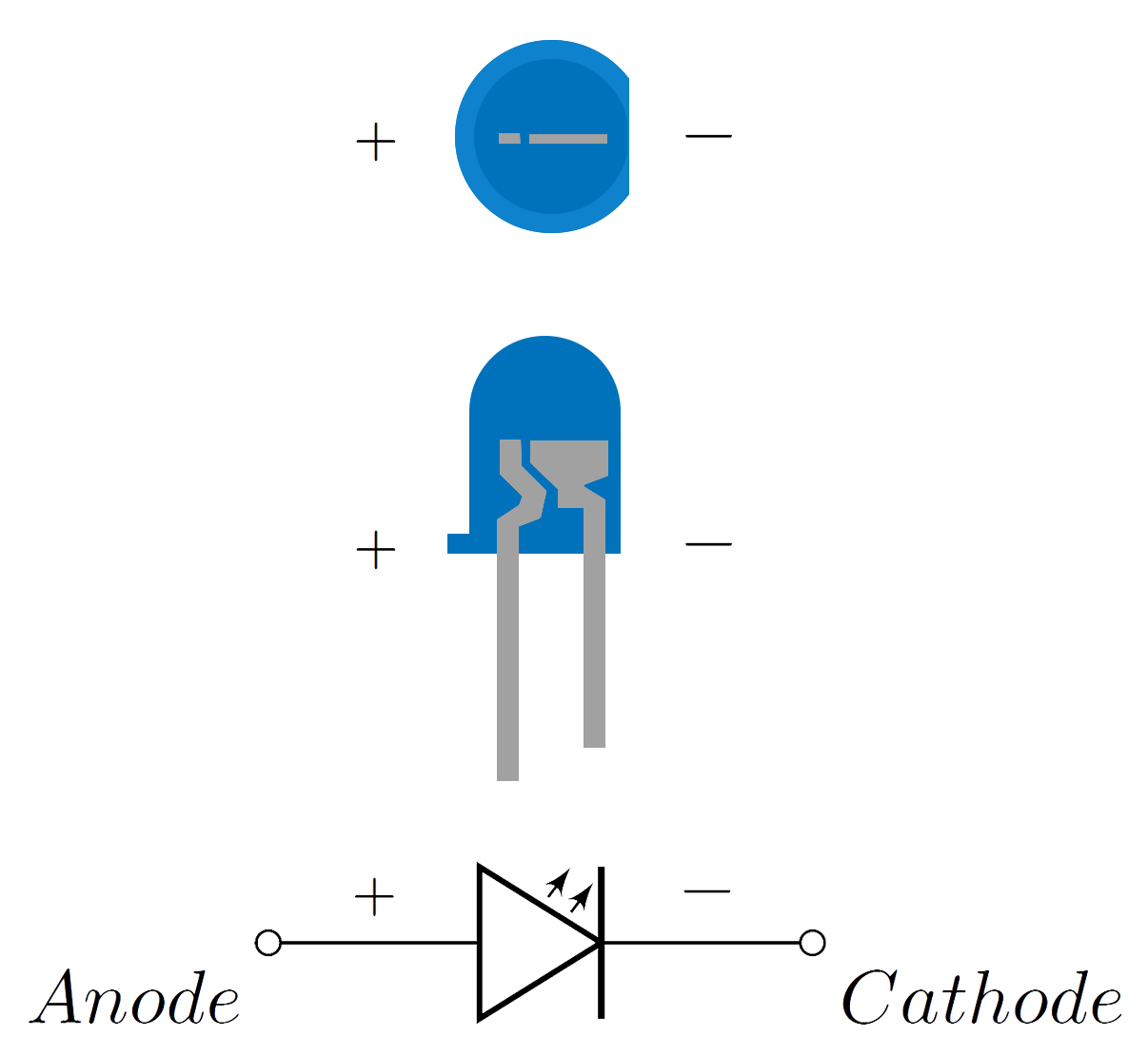
LEDs have polarity. This means that LEDs have to be connected in a certain way, and not the reverse one. They have a positive side, called anode, and a negative side, called cathode. We can light them up by applying a positive voltage difference on the anode and cathode. Apply an excess voltage, and the LED will burn. Apply a negative voltage, and the LED won't lit.
LEDs have a specific voltage (a.k.a. forward voltage) on which they like to be operated. On the forward voltage, they light up in full brightness. If we give them a smaller voltage, they will still work, but they will just be less bright. We can't operate an LED directly on voltages bigger than the forward voltage. If we can't supply the (forward) voltage needed, we can still make use of a higher voltage by adding a current limiting resistor.
Different LEDs, in size and color, have different forward voltages. Though, we don't necessarily have to look for the forward voltage of every LED we use. For the 5 mm (or 3 mm) round LEDs (of any color) and a \(5V\) supply, a \(470\Omega\) resistor will always be a safe choice.
If we want to make sure that our LEDs will light up in full brightness, we have to pick an appropriate current limiting resistor for the specific forward voltage of the LEDs.
One more parameter of an LED is the current (a.k.a. forward current) it draws when it operates on the forward voltage. You can find both the forward voltage and current of your LED on its datasheet.
Let's call the LEDs' forward voltage, \(V_{f}\), and the LEDs' forward current, \(I_{f}\). Then, we can calculate the resistor needed to operate our LEDs in full brightness, with the following equation
\(R = \frac{5V - V_{f}}{I_{f}} [\Omega]\).
Let's say we have some LEDs with a \(V_f = 3.1V\) and a \(I_f = 20mA\). Then, the resistor needed is \(R = \frac{5V - 3.1V}{0.02A} = 95 \Omega\). There is no \(95\Omega\) resistor, so we choose the closest realizable higher valued resistor. That is \(100\Omega\). Now, we pick some \(100\Omega\) resistors, we use one resistor for every LED, we apply a \(5V\) voltage difference to the LED-resistor combos... and finally the LEDs will light up in full brightness.
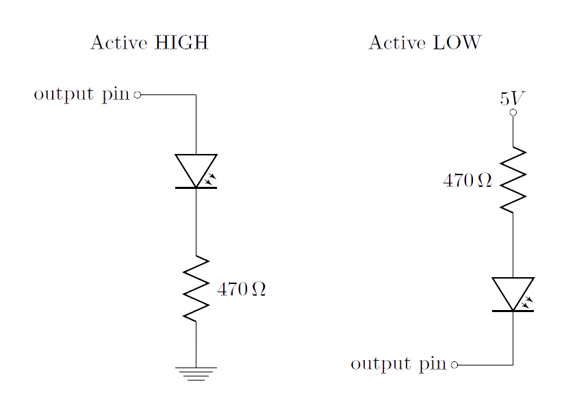
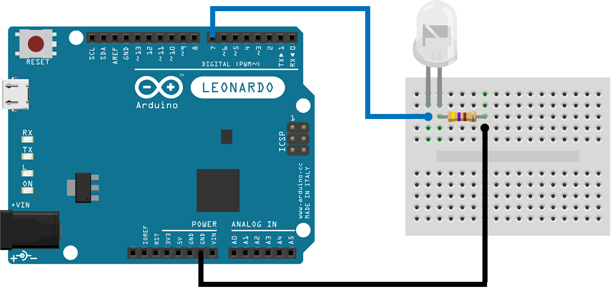
If we connect the anode of an LED to an output pin of an Arduino, we can turn the LED on by writing HIGH to the pin. If we connect the cathode of an LED to an output pin of an Arduino, we can turn the LED on by writing LOW to the pin.
Let's write some code now. We'll start with the famous blink example. This example uses an LED and an output pin on an Arduino to control the LED. In the code, we turn the LED on for a second, then we turn it off for another second, and then we repeat.
Make the following connections with the LED, the resistor and the Arduino. Pay attention to the polarity of the LED. The cathode connects to the resistor and the anode to the output pin on the Arduino. Connect the Arduino to your computer with a USB cable, upload the code, and watch the LED flash every two seconds.
Buzzers
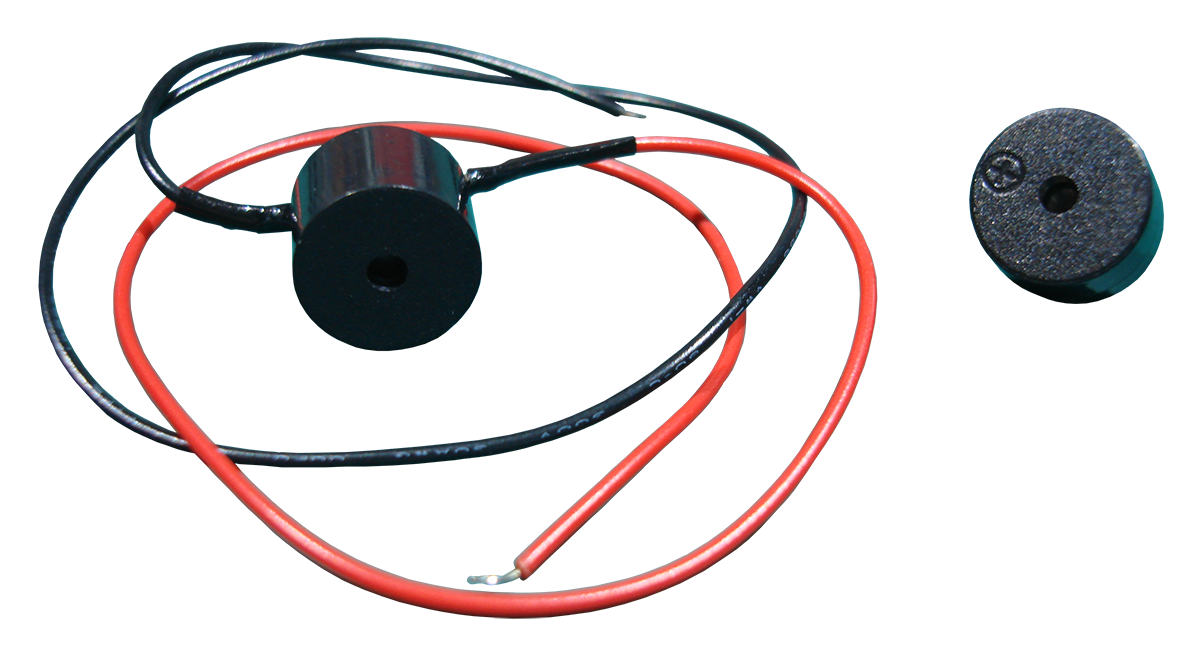
The next component we will handle is the buzzer (a.k.a. piezo buzzer). I'm sure you heard a buzzer beeping before, like when you start your desktop computer and a short beep sounds to indicate normal hardware conditions, or when a truck has put on reverse to notify the people around it. Another common application of buzzers is for user input confirmation on keystrokes. If you want to know more about the operation of a buzzer, you can read the article at the engineersgarage.com.
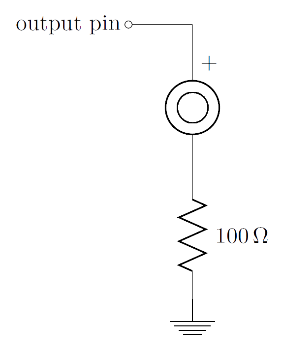
A buzzer has polarity. The positive side always goes to a higher voltage than the negative side. You should normally use a buzzer with a \(100\Omega\) resistor at \(5V\).
The example below is basic demonstration of the operation of a buzzer. It just plays a series of beeps, repeatedly.
If you want to do something more interesting with a buzzer, look at the tone() and noTone() functions that let you excite the buzzer at different frequencies, thus creating notes and being able to compose music. Check them out
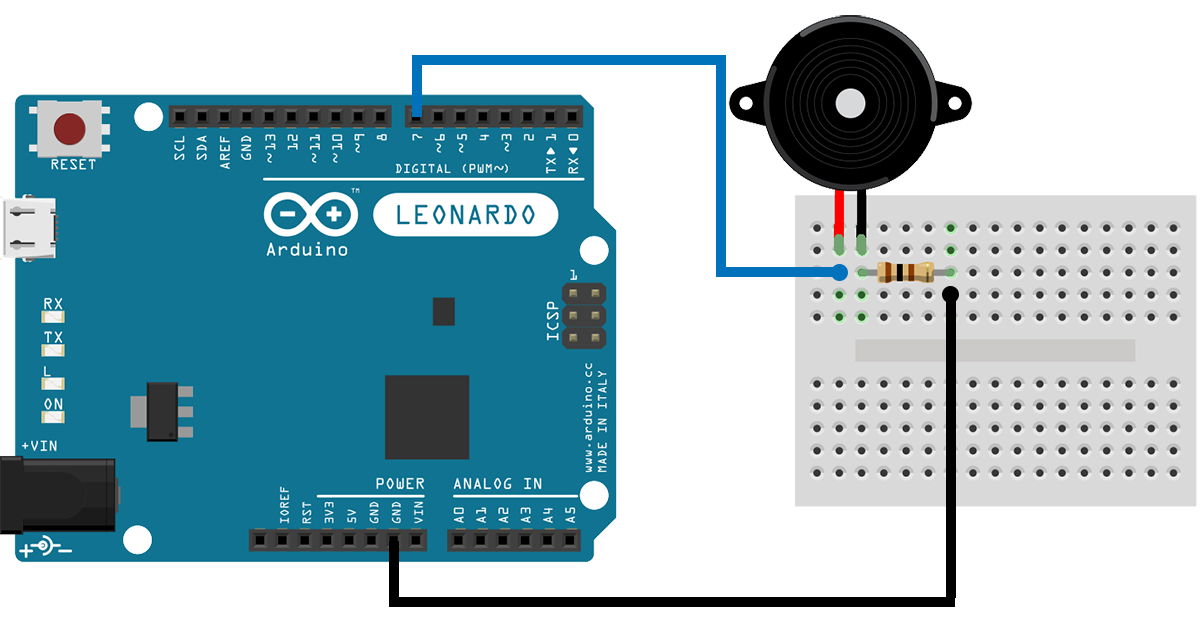
Make the following connections with the Arduino, the buzzer, and the resistor. Pay attention to the polarity of the buzzer. Positive (+) side goes to the output pin on the Arduino. Connect the Arduino to your computer and upload the code. You should hear two short beeps and one long beep repeating.
Conclusion
In this tutorial you've learned about LEDs and buzzers. At this point, you know how to connect them and how to use them. Now clone the examples to your account, try out some variations in the code, and see how it all works out. We'll get back next time with some new components!
The Schematics were based on fritzing.
Images are CC BY-NC-SA 3.0.
Article Tags
Categories
- Advanced Tutorials [10]
- Basic Tutorials [52]
- Developers say [31]
- Events [15]
- Features Recap [7]
- Fun Times [7]
- News [3]
- Tech Stuff [93]
Archives
Tags
- 1sheeld 1
- 2015 1
- 7 segment 1
- 74hc4067 1
- 74HC595 1
- A7corsair 1
- academy 1
- ace editor 1
- acquisition 1
- actuator 1
- adafruit 7
- adc 1
- adding files 1
- additions 1
- airboard 1
- alarm 1
- alert 1
- altimeter 1
- analog 2
- analog read 1
- analogRead 1
- anode 1
- app update 1
- Arduboy 1
- arduino 72
- Arduino Day 1
- arduino tone 1
- ArduinoD16 1
- Assetic 1
- async 2
- august 1
- automation 1
- aws 4
- awscli 1
- back end 1
- backup 1
- Badgerhack 1
- Badgerstick 2
- barometric pressure 1
- battery 2
- baud rate 2
- benefits 1
- blink 2
- blynk 1
- bmp280 1
- board 9
- boards 1
- boost 2
- boto 1
- bounce 1
- breadboard 1
- Brussels 1
- button 6
- button switch 1
- buzzer 2
- c++ 1
- card 1
- casperjs 1
- cathode 1
- celebration 1
- cell 1
- ch340 1
- ch340g 4
- ch341 1
- ch341g 1
- ch34x 1
- chai 1
- charge 1
- charger 1
- checksum 1
- christmas 2
- chrome 1
- chrome app 1
- chromebook 1
- chromeos 1
- circuit playground 1
- click 1
- clock 1
- closures 2
- code review 1
- codebender 127
- coding 2
- collaboration 1
- comments 1
- community 1
- compiler 3
- control 2
- converter 2
- crowdsource 1
- current 1
- curve 1
- dac 1
- data 1
- datapoints 1
- date 1
- day 1
- debounce 1
- debouncing 1
- demultiplexer 1
- dependency injection 1
- description 1
- design 1
- designer 1
- dev 2
- developer 10
- developers 1
- developers say 3
- devops 1
- DHT-11 1
- digital 2
- diode 1
- display 1
- disqus 1
- distance 1
- diving 1
- doctrine 1
- dome 1
- door 1
- driver 1
- drivers 6
- ds1307 1
- ds18b20 1
- editor 3
- education 1
- el capitan 1
- electronics 1
- emic2 1
- escape 1
- europe 1
- event 5
- events 1
- examples 2
- facebook 1
- fade 3
- fakedrake 2
- fast 1
- feature 3
- features 4
- features recap 6
- file 1
- finder 1
- fio 1
- firefox 1
- fitting 1
- flex resistor 1
- flex sensor 1
- flora 2
- FM 1
- FM Radio 1
- force 1
- FOSDEM 1
- fsm 1
- fuel 1
- fun 1
- fun times 3
- games 1
- gaming 1
- gas sensor 1
- gauge 1
- gemma 1
- Genuino Day 1
- GenuinoD16 1
- github 1
- go kart 1
- GP2Y0A41SK0F 1
- group 1
- guzzle 1
- hackathon 1
- HC-SR04 1
- HDT-22 1
- hiring 1
- homepage 1
- http client 1
- Humidity 3
- hummingbirdduo 1
- hygrometer 1
- i2c 1
- IDE 1
- include 1
- infrared 3
- input 3
- install 1
- installer 1
- interaction 1
- interrupt 1
- ion 1
- iOS 1
- IoT 1
- ir 2
- irranger 1
- isp 1
- javascript 3
- job 1
- july 1
- karma 1
- kext 1
- keypad 2
- kit 1
- kocoafab 1
- l293d 1
- L298 1
- landing page 1
- lcd 2
- LDR 1
- learning 1
- led 9
- Let's Start Coding 1
- libraries 4
- library 5
- lifuelgauge 1
- light 2
- lightup 1
- lipo 2
- list 1
- lithium 2
- littleBits 1
- load 1
- logging data 1
- LoRa 1
- LoRaWAN 1
- lowpowerlab 1
- lux 1
- mac 1
- Mac installer 1
- mac osx 1
- machine 1
- MacOSX 1
- magnetic 1
- Makeblock 1
- maker 1
- Maker Board 1
- maker faire rome 2015 1
- makercon 2
- makerfaire 4
- makers 1
- makey 1
- makezine 1
- map function 1
- marsone 1
- matlab 1
- matrix 1
- max7219 1
- max7221 1
- mCore 1
- ME Orion 1
- mega 1
- message 1
- message queue 1
- messaging 1
- metaprogramming 1
- microcontroller 1
- mocha 1
- model 1
- module 2
- moteino 1
- motor 2
- motor driver 2
- MQ gas 1
- multiple sessions 1
- multiplexer 1
- mux 1
- neomatrix 1
- neopixel 4
- new 8
- New board 9
- new boards 1
- new editor 1
- new feature 4
- new features 5
- new homepage 1
- new members 1
- new offices 1
- new plug in 1
- new stuff 4
- new year 1
- news 3
- node.js 1
- npn 1
- NSIS 1
- on boarding 1
- online IDE 1
- open 1
- opsworks 1
- option 1
- OrangeBoard 1
- OrangeBoard BLE 1
- ornament 1
- osx 1
- output 3
- P2N2222A 1
- PackageMaker 1
- page loader 1
- paintball 2
- pairing 1
- parameters 1
- parity 1
- partner 1
- partnership 1
- peer review 1
- personal libraries 1
- photocell 1
- photoresistor 1
- php 2
- phpunit 1
- piezo 1
- pioneer 1
- pitch 1
- plug in 3
- plugin 3
- polarity 1
- pole 1
- polymer 1
- position 2
- pot 1
- potentiometer 2
- power 2
- pro trinket 2
- process 1
- programming 2
- project view 1
- projects 1
- promicro 1
- protocol 2
- pull 1
- push 1
- pwm 3
- pytest 1
- python 4
- qmetric 1
- queues 1
- Radio 1
- ram 1
- range 1
- ranger 1
- RDS 2
- real 1
- receiver 1
- remote 1
- resistor 2
- rfid 2
- rgb 2
- ring 1
- robot 1
- room 1
- rotation 1
- rqbbitmq 1
- rtc 1
- Safari 2
- saucelabs 1
- scroll 1
- scrolling 1
- sd 1
- search 2
- seeed studio 2
- Seeeduino Mega 1
- Seeeduino Stalker 1
- segment display 1
- selenium 2
- sensor 12
- serial monitor 2
- servo 1
- seven segment 1
- shake switch 1
- sharp 2
- sharpirlib 1
- shield 2
- shift register 1
- si4703 1
- signal 2
- signing 1
- sinon 1
- sketch 1
- soc 1
- soil 1
- sort 1
- sorting 1
- sound 1
- sparkfun 3
- sparki 1
- speaker 2
- speech 1
- speed 1
- sshfs 1
- state 1
- STEM 1
- strip 2
- stuff 1
- switch 2
- symfony 3
- symfony2 4
- tag 1
- TEA5767 1
- tech 3
- tech stuff 1
- technical 2
- temperature 5
- templates 1
- teslakit 1
- testing 3
- tests 1
- text 1
- The AirBoard 1
- The Things Network 1
- The Things Uno 1
- TheAirbord 1
- thermistor 1
- threshold 1
- throw 1
- time 2
- tiny 1
- tiny circuits 1
- tinyscreen 1
- tmp36 1
- transistor 1
- transition 1
- tree 1
- trinket 2
- tsl2561 1
- tutorail 1
- tutorial 54
- tutorials 1
- type systems 1
- uart 2
- Ultrasonic 1
- unit tests 1
- update 5
- updates 4
- usb 1
- variable 1
- variable resistor 2
- vendor 1
- vibration 1
- voice 1
- voice commands 1
- voice module 1
- voltage 1
- volume 1
- walkthrough 1
- water flow 1
- water level 1
- wearable 1
- websockets 1
- wicked device 1
- wiegand 1
- wifi 1
- wildfire 1
- windows 2
- windows drivers 1
- wire 1
- wireless 1
- wishes 2
- wizfi210 1
- xmas 1
- yosemite 1