Big Dome Button - NeoPixel Ring Tutorial from codebender on Vimeo.
This is a tutorial on how you can upgrade a Big Dome button by adding a NeoPixel ring, enabling it that way to accommodate user interaction capabilities. You can find the Big Dome button at Sparkfun, and the 16LED NeoPixel ring at Adafruit.
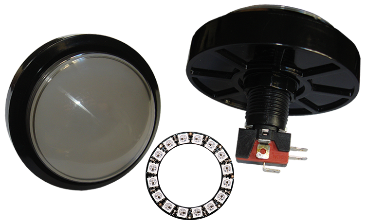
Why adding a NeoPixel ring in the button will enable user interaction capabilities you ask? Well, RGB LEDs are not only good for creating just visual effects. You could also use different color sequences to signify various events. Say your doorbell rings or your food is ready, you have a message on your phone or you have an upcoming appointment, and you are wearing headphones or you are too focused on your work to notice anything. Then, one solution to the problem is to create some visual signals that your eyes can catch. And the NeoPixels are powerful enough that can light up an entire room. So, have no doubts, you will notice them.
For details on how to modify the Big Dome button watch the video above.
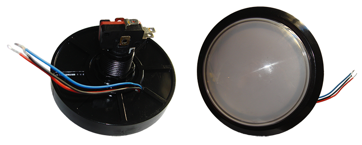
This is the finished button with the NeoPixel ring embedded in it.
Let's see how the button is performing.
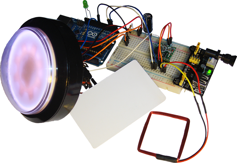
This is the system that we will build. Last week we presented the RFID library, and we showed how you can read RFID tags. Now, suppose that you have built an RFID enabled door, you have shared the RFID tags with your peers, but you think the whole system is too boring and you want to make it more fun. That's when you decide to play a prank on the tag holders. You will use the button to let it inform you when someone has opened the door, and then press the button if you want to give them a scare. How you are going to do that it's up to you. An LED is used for the demonstration.
Let's do this. Make the following connections.

The resistor is 10K and the capacitor is 1000uF.
Upload the Big Dome Button - NeoPixel Ring example to your Arduino... and watch the system in action.
The code checks if the RFID reader has read any tags, and if so, it gives a visual signal with the ring. If the button is not pressed within 5 seconds, there will be a time out and a different signal will appear on the ring to tell you that you missed the event. Then, you can press the button once to reset. If you press the button within the time limit of 5 seconds, the actuator pin will go high and whatever device you have connected on that pin will get activated. And lastly, if the system is on standby and the button is pressed, nothing will happen.
There are a couple of things to remember here. Doing visual effects with the ring occupies entirely the Arduino. So in our case, it might be that we are unable to check whether the reader has sent any data. There are two ways of dealing with this issue. We can try to hack our way out of it by writing a really complicated and messy code that will break the color sequences and embed the various checks in between parts of a color sequence, or we can just distribute the system by assigning a dedicated controller to the NeoPixel ring.
The other issue is that the LEDs inside the button are getting really hot, and at some point they stop responding. So, don't set their brightness too high, and if you still have problem try applying a heatsink or drilling some more holes.
That's all folks. We hope you enjoy the project, and if you have any comments or suggestions you can contact us at girder [at] codebender [dot] cc
Sounds are from freesound.org. Schematics were based on Fritzing.