MUX74HC4067 Tutorial from codebender on Vimeo.
This is a tutorial on the MUX74HC4067 library.
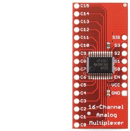
The name of the library refers to the IC that is on the Analog/Digital MUX Breakout from Sparkfun. This IC is a 16-channel analog multiplexer/demultiplexer. You can think of it as an SP16T switch that is digitally controlled. You position the switch by writing to the control pins and then you let the data flow in either direction.
You can use this module to increase the number of inputs and outputs on your Arduino, since it only needs 6 or 5 pins to provide access to 16 data lines. You could connect to these 16 lines... sensors, buttons, transistors to control relays, or even serial lines from other Arduinos.
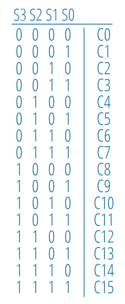
The SIG pin connects to any of the 16 channels, C0 - C15. S0 to S3 are the control pins. You write to these pins a binary code, and the corresponding channel is selected. For example, by writing 1010 to S3 S2 S1 S0, the C10 channel gets connected to the SIG pin.
There is also the EN pin that if driven HIGH, it disables the connection of the SIG pin with any of the 16 channels.
The maximum current that can go through a channel is 25 mA. If you need to power things like relays, solenoids, or motors, you will need to use transistors, and pass through the channels only the control signals.
readDigitalSignals
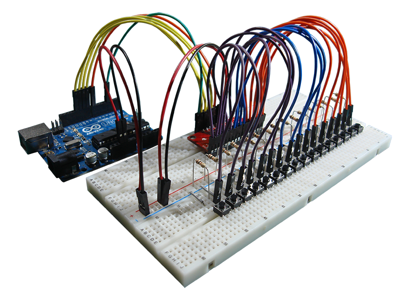
This example assumes there are push buttons with pullup 10 kOhm resistors connected to the 16 channels like in the following figure.
The code reads the input from all the channels, one after the other, and prints on the serial monitor a statement about whether a push button is pressed or not.
All you have to do is declare a MUX74HC4067 instance, configure as a DIGITAL INPUT the Arduino pin to which the SIG pin connects, and you are ready to read from the channels. Just call read with argument the channel number and read will return either LOW or HIGH.
readAnalogSignals
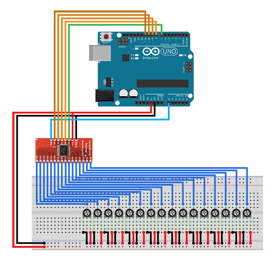
This example assumes there are potentiometers connected to the 16 channels like in the following figure.
The code takes measurements of the potentiometers' values and prints on the serial monitor a statement about that value.
By configuring the signal pin as an ANALOG INPUT and then calling read, you get back the value measured by the A/D converter. It's an integer from 0 to 1023.
writeDigitalSignals
This example assumes there are 16 LEDs with current limiting 150 Ohm resistors and the positive leads of the LEDs are connected to the 16 channels like in the following figure.
The code just lights up the LEDs, one after the other. You configure the signal pin as a DIGITAL OUTPUT and then you write to a channel by calling the write method and providing as arguments the channel number and a LOW or HIGH value.
writePWMSignals
The circuit for this example is identical to the previous one. The difference here is that the output to the LEDs is a PWM signal.
You can output a PWM signal, by configuring the signal pin as an ANALOG OUTPUT and then calling the write method and providing as arguments the channel number and a value (0 to 255) for the duty cycle of the PWM signal.
That's all folks. We hope you enjoy this library, and if you have any comments or suggestions you can contact us at girder [at] codebender [dot] cc
Sounds are from freesound.org. Schematics were based on Fritzing.


