
Time for some more components. This time we look at resistors. Fixed value resistors and variable resistors. Resistors that depend on position, rotation, light, pressure, temperature, and others. We'll take a look at some of them, and see how they operate. Let's dive right in...
Resistors

Resistors, as their name suggests, are components that can resist. But resist to what? Resistors are used to resist current flow. They are also used to resist to excessive voltages. Or, in other words... to limit voltage levels within a circuit. Or, in other even better words... to control voltages. Maybe you have a component that is sensitive to current. Then add a resistor to make sure that it won't get burned, like we saw the previous time with the LEDs. Maybe you need a specific voltage level that is not available to you. Then use some resistors to create one.
Resistors come in a variety of values, measured in ohms, \(\Omega\). The bigger the value, the more they can resist. But they don't do magic. They can only take so much current in, before they give up. Or to put it in more technical terms, there is a limit in the amount of power they can dissipate. So resistors also have a value measured in watts, \(W\). And as a matter of fact, all components out there do.
Let's say we have a AA battery that has a \(1.5V\) output voltage, and we connect a \(4.7\Omega\) resistor (often written as, \(4R7\)) to the battery's leads. From Ohm's Law, \(V = RI\), we calculate the current that will go through the resistor as, \(I=\frac{V}{R}\) \(=\frac{1.5V}{4.7\Omega}\) \(=0.319A\) \(=319mA\). The power that the resistor will consume is \(P=VI=I^2R\) \(=(0.319A)^2\times(4.7\Omega)\) \(=0.48W\). So the \(0.5W\) resistors that you will commonly use every day, will barely do.
![]()
Voltage Dividers
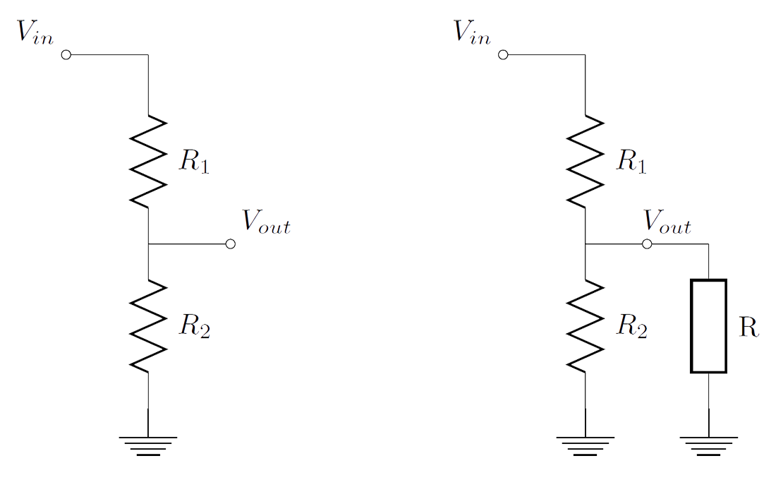
One very common use of resistors is for making voltage dividers. A voltage divider is a circuit that takes in a voltage, and divides it to output a fraction of that voltage. Let's say, we have the first circuit of the figure above. Then, the output voltage is \(V_{out}=\frac{R_2}{R_1+R_2}V_{in}\). So, picking the right resistor values for \(R_1\) and \(R_2\), we can create any voltage level we want, between \(0\) and \(V_{in}\).
To derive the voltage divider equation we'll need to refer to Kirchhoff's Voltage Law (KVL) and Ohm's Law. KVL says that the sum of the voltages in a circuit loop is zero. So for the voltage divider, we have \(V_{in}-V_1-V_2=0\) \(\Leftrightarrow\) \(V_{in}=\) \(V_1+V_2\) \(=R_1I_1+R_2I_2\) \(=(R_1+R_2)I\) \(\Leftrightarrow I=\frac{V_{in}}{R_1+R_2}\). We know that \(V_{out}=V_2\). From Ohm's Law, we have \(V_2=R_2I\). So, the output voltage is \(V_{out}=R_2I\) \(=R_2\frac{V_{in}}{R_1+R_2}\) \(\Leftrightarrow V_{out}=\frac{R_2}{R_1+R_2}V_{in}\).
But, just a minute... does this mean that I can take the \(5V\) output from my USB cable, use a voltage divider to make a \(3.3V\) output, and power my Arduino Pro Mini? Certainly not! Resistor arrangements, like in the voltage divider, are used only for something called signal processing. They are used to manipulate (process) information in the form of an electrical signal. So, we might use for example a voltage divider to convert the \(5V\) analog output of a sensor to a \(3.3V\) analog output, so the Arduino Pro Mini, I mentioned before, can read it.
But what exactly is the problem with using a voltage divider to supply power to another device? First of all, resistors waste energy. Remember that the power consumed by a component is analogous to the square of the current through it, \(P \propto I^2\). So, the more current we drive through a resistor, even more energy gets thrown away. This is bad! Second of all, under high loads, the output voltage is bound to change. So, we have to find a more reliable means of converting voltages. For that we need to devise special circuits. This is a very interesting area of power electronics that is also way way beyond the scope of this tutorial. If curious, google for buck or boost converter.
Let's look at the second circuit in the figure above. We have connected a load \(R\) to the output. Let's pick some values and see what happens. For the input voltage, we have \(V_{in}=5V\). For the resistors, we have \(R_1=1K\) and \(R_2=1K8\). So, the output voltage should be \(V_{out}=\frac{1800}{1000+1800}5V\) \(=3.2V\). But let's consider now, a \(R=10\Omega\) load. The resistor \(R_2\) and the load \(R\) appear in parallel. We can think of this resistor combination as an equivalent resistor with value \(R'=\frac{R_2R}{R_2+R}\). This equivalent resistor will be \(R'=R_2//R=\frac{1800\times10}{1800+10}\) \(=9.94\Omega\). And considering the voltage divider equation again, we get \(V_{out,new}=\frac{R'}{R_1+R'}V_{in}\) \(=\frac{9.94}{1000+9.94}5V\) \(=0.049V=49mV\). Oops!
Now you know. So, don't even think about it.
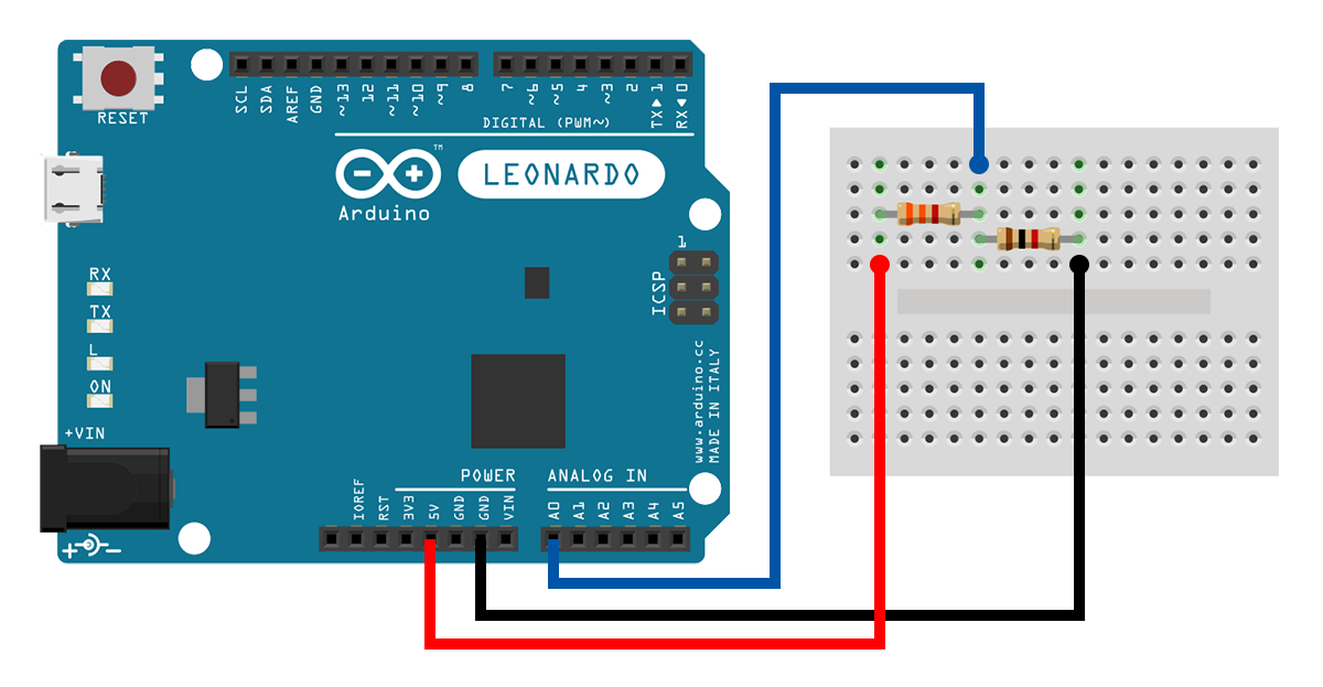
Let's build a quick example project to make sure that we are not mistaken about voltage dividers. Pick a \(R_1=3K3\) resistor and a \(R_2=1K\) resistor. Then make a voltage divider circuit, like in the following schematic. We expect a voltage output, \(V_{out}=\frac{1000}{3300+1000}5V=1.16V\).
The code makes use of the Serial library. We'll talk about serial communication in a future tutorial. For now, all you have to know is that your Arduino will send some data to your computer. So, clone the example to your account, upload the code to your Arduino, and open the Serial Monitor. Do you see what you expected? Do you see a value around \(1.16V\)? And I say "around", because remember... resistors have tolerances.
Potentiometers
Potentiometers are variable resistors. They can be used as user input to adjust some other output variable, like the volume of the speaker, or the intensity of an LED. They come in a number of forms, but basically they all work in the same way: we change their value by altering a characteristic of theirs. In our case, we'll use a trimpot, and so we operate it by rotating its shaft. They are 3-lead components. On the outer leads, we provide a voltage difference, and on the middle lead, they output a fraction of that voltage. Does that sound any familiar to you? I bet it does... potentiometers are indeed voltage dividers. What's special about them though is that their resistors are complementary. Increasing one resistor, decreases the other.
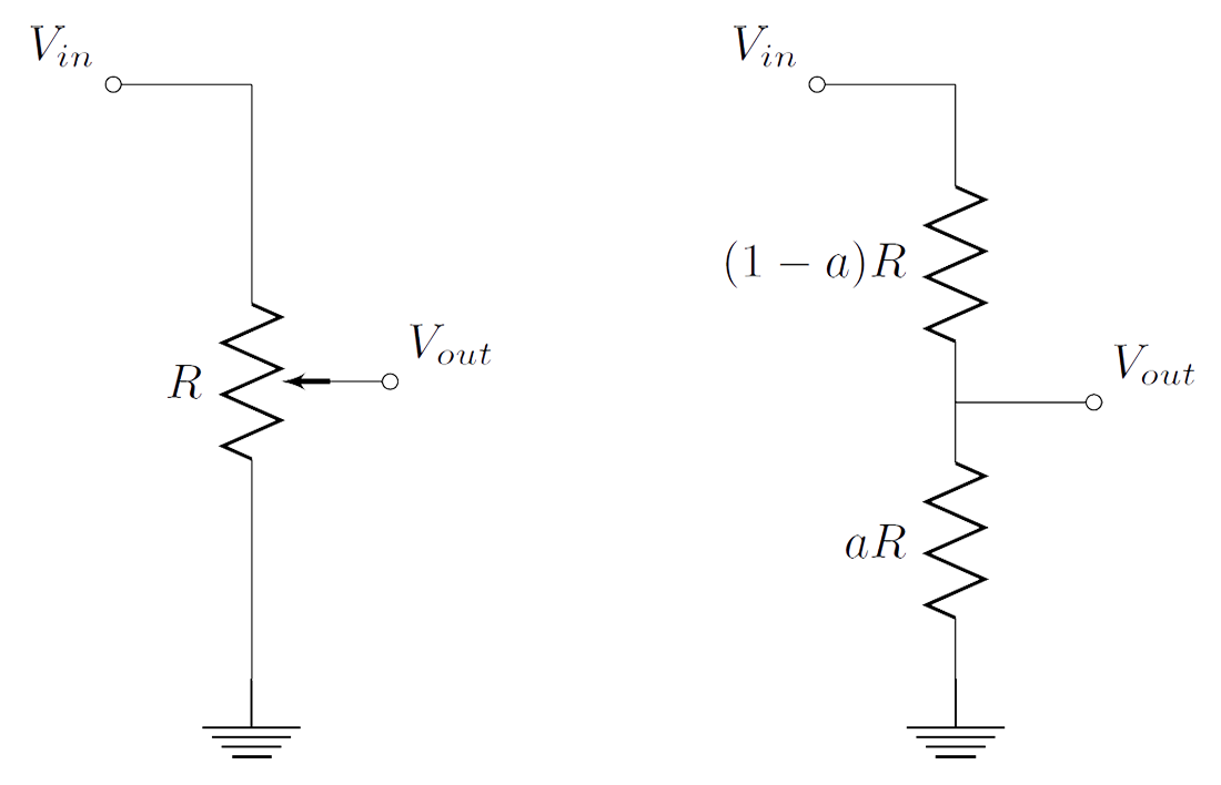
Potentiometers (pots) too have a resistance indication, measured in \(\Omega\). This value is their total (maximum) resistance (\(R\) in the figure). When we say we change the value of a potentiometer, we really change that \(a\) coefficient shown in the figure above. Rotate the shaft of a trimpot clockwise, and \(a\) increases. Rotate counterclockwise, and \(a\) decreases. Let's see this in action.
pot_video from codebender on Vimeo.
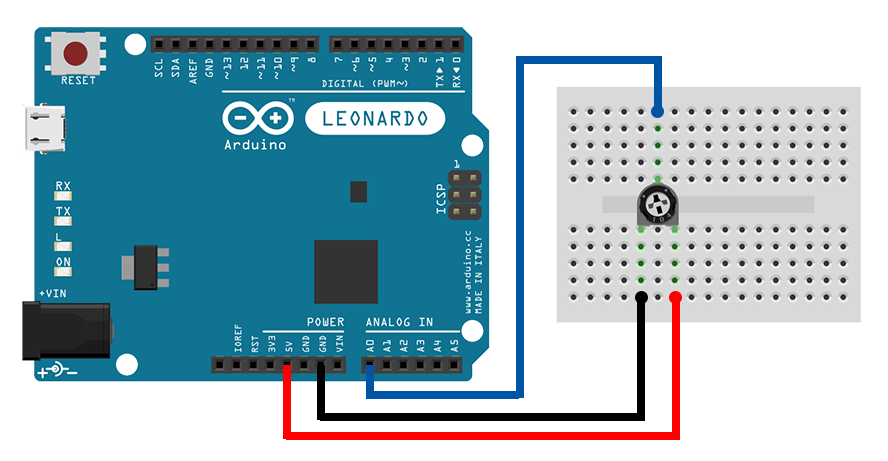
Now it's your turn. Take a \(10K\), or so, trimpot, and connect it to your Arduino, like in the following schematic. Then, clone the example to your account, upload it to your Arduino, open the Serial Monitor, and see how the values change as you rotate the trimpot's shaft. You see the value of the A-to-D converter, ranging from 0 to 1023. Do you know how to convert those values in volts? You saw it in the previous example. Give it a try!
Light Dependent Resistors
LDRs are resistors that change their value with light. They decrease their resistance with incident light intensity. They can be used in tasks like detecting the night phase of the day and taking appropriate actions.
In the following video, I'm using an LDR as the \(R_1\) resistor in a voltage divider. You can see that as I bring the LDR under the shadow of my finger, its resistance increases, and so the output (that you see on the graph) of the voltage divider decreases.
ldr_video from codebender on Vimeo.
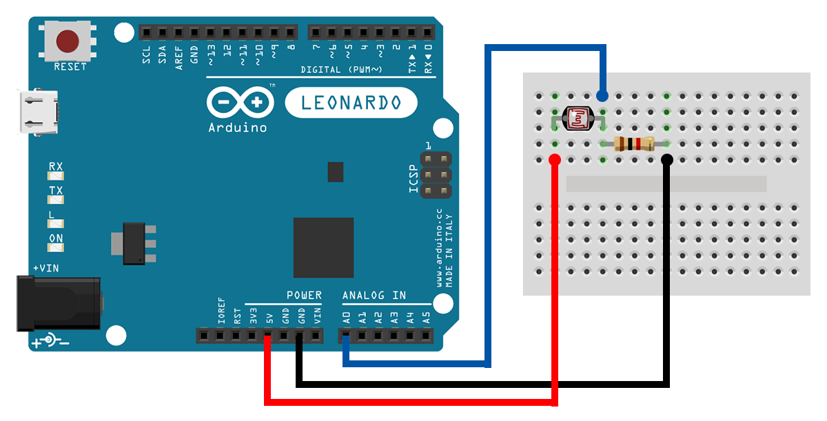
Now, you go. Make the connections shown in the following schematic. It's a voltage divider with an LDR as the \(R_1\) resistor and a \(1K\) resistor as the \(R_2\) resistor. Do the usual procedure "clone, upload, open", and see how the values are changing as you shine light on the LDR.
Thermistors
Thermistors are variable resistors that depend on temperature. They can be used with air conditioners, in water lines, in your oven, anywhere you might think you need to control the temperature or take actions based on it. Thermistors have a resistance value that is given for a specific temperature, e.g. \(10K\) in \(25^oC\). There are two types of thermistors, NTC and PTC. NTC thermistors decrease their resistance with increasing temperature, and PTC thermistors increase their resistance with increasing temperature.
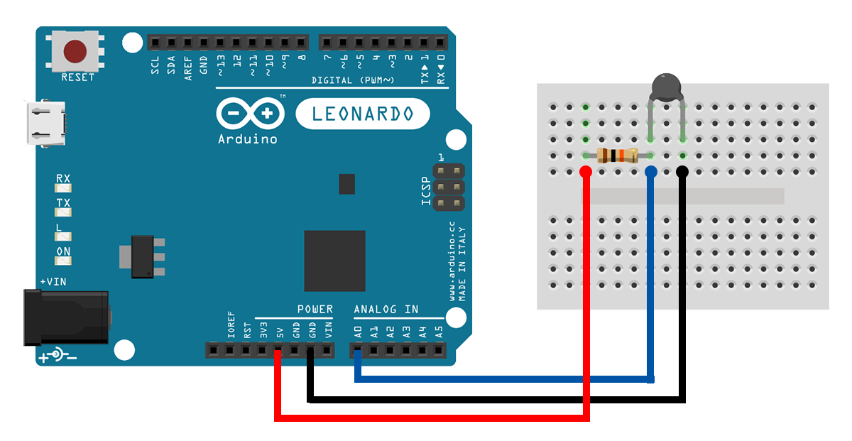
In the following video, I'm using a NTC thermistor as the \(R_2\) resistor in a voltage divider. You can see that as the lighter burns next to the thermistor and its temperature increases, its resistance falls. And then after I remove the lighter, the resistance climbs back up again.
termistor_video from codebender on Vimeo.
Nothing more to say... you know the drill ;)
Touch the thermistor with your fingers, then wait and see. Does its resistance changes?
Conclusion
This time it was all about resistors. There are many more types out there. Commonly, they are pretty cheap, so go out, buy some, and experiment. There is a wide range of applications, and you can think of your own. See you next time with some more components!
The Schematics were based on fritzing.
Images are CC BY-NC-SA 3.0.