Introduction
In this tutorial you will learn how to use a shift register (or serial to paralled controller). The shift register will give to your Arduino an additional 8 digital outputs, by using only 3 pins on your board
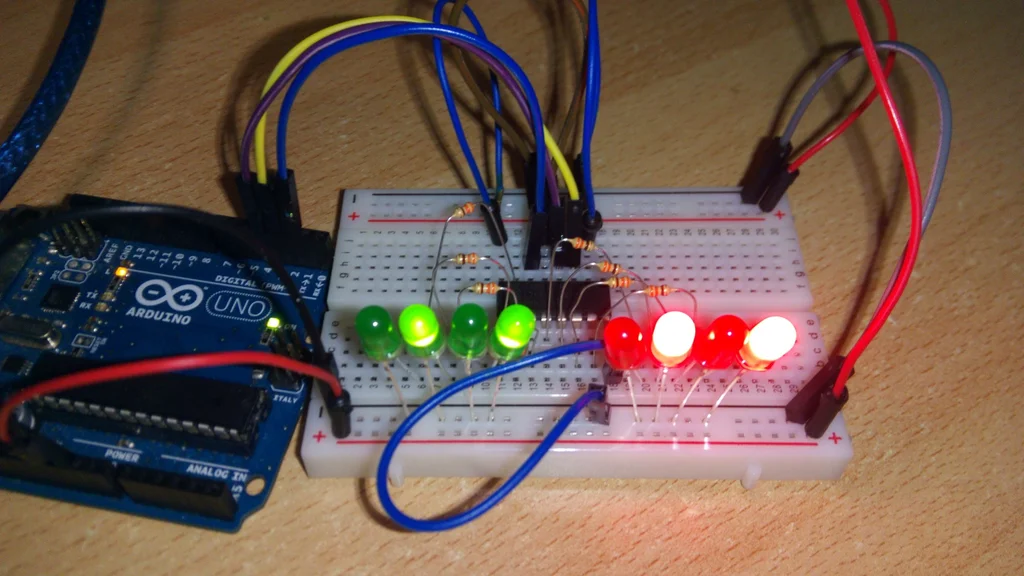
In this tutorial you will practice by using the shift register with Arduino uno to control 8 LEDs.
So, let's get started!
What you will need
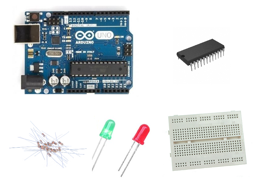
For this tutorial you will need:
- Arduino uno
- Breadboard
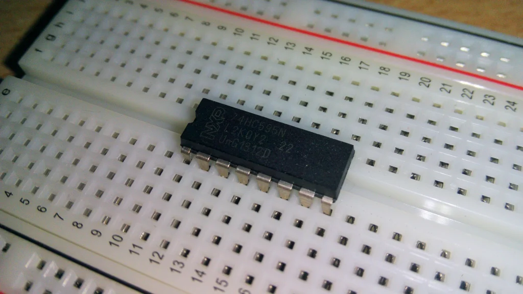
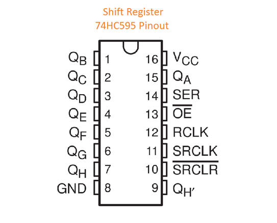
- Shift Register IC (74HC595)
- 4x Red LEDs
- 4x Green LEDs
- 8x 330 Ohm (or 220) resistors
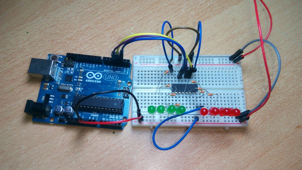
The Circuit
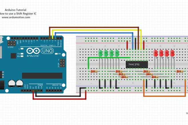
The connections are easy, see the image above with the breadboard circuit schematic.
You can find more info about IC here: datasheet
The Code
Here's the code, embedded using codebender!
We will use example sketch from ShiftRegister74HC595.h library.
How it works:
sr.setAllHigh();Turn all LEDs onsr.setAllLow();Turn all LEDs offsr.set(i, HIGH);Turn LED i on (0 < i < 7)uint8_t pinValues[] = { B10101010 };sr.setAll(pinValues);Binary to turn on 2nd,4th,6th and 8th LED
Try downloading the codebender plugin and clicking on the Run on Arduino button to program your Arduino with this sketch. And that's it, you've programmed your Arduino board!
You can make your own modifications to the code by clicking the "Edit" button. For example, try to change line: uint8_t pinValues[] = { B10101010 }; with uint8_t pinValues[] = { B11001100 };
Well done!
You have successfully completed one more "How to" tutorial and you learned how to use a shift register ic with Arduino.