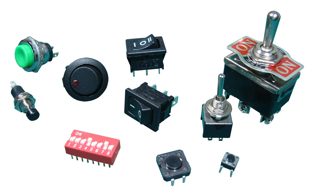
TV, laptops, phones, printers, alarms, cars, toys... they all have one common thing. They all need to be turned on and off, and so they all have at least one switch on them. Switches are the most simple and direct form of user input for any kind of device. They let the user give a clear instruction to a device, so the device in turn can respond appropriately. There are several types of switches, in different forms and sizes, and in this tutorial we will examine the most common among them.
Switches

A switch, in its simplest form, is a set of contacts. This set of contacts can either be connected or not... we say those contacts are closed and open, respectively. There will always be a mechanism actuating the transition between these two states. When a switch is closed, it forms a short-circuit and lets current flow through it. When it's open, no current goes through.
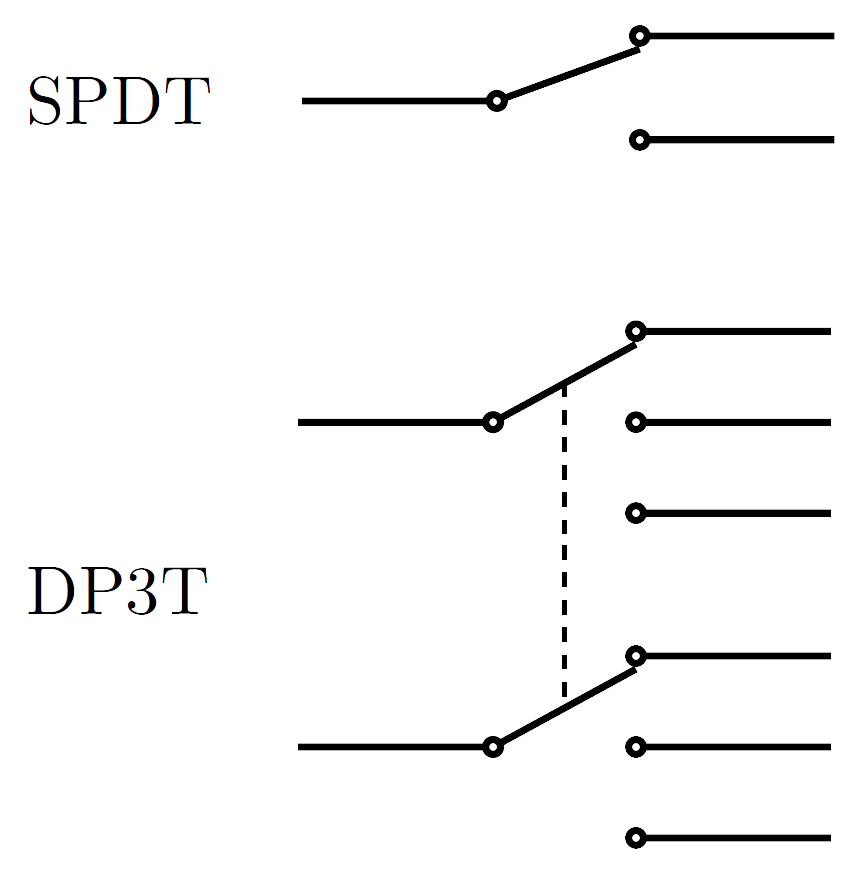
Switches are characterized by the number of contacts and how those contacts are laid out. There are two terms, pole and throw, that distinguish the various switches between them. You can think of a pole as a corridor, and a throw as a door at the end of the corridor. You walk down the corridor and if the door is open, you go through. This analogy corresponds to the switch I described above, and that switch is called SPST, for Single Pole Single Throw. If that corridor has two doors at the end, then you can choose which door to open. This corresponds to a SPDT (Single Pole Double Throw) switch. Now, if you think of two corridors and three doors at each end, then you get a DP3T switch. Both those switches are shown in the figure to the right.
A switch with more than one pole always picks the same throw (position) for each individual pole. That's what the dashed line in the figure is for... to declare dependence. If you want to control the throws independently, then you should buy several single pole switches, and not one with multiple poles.
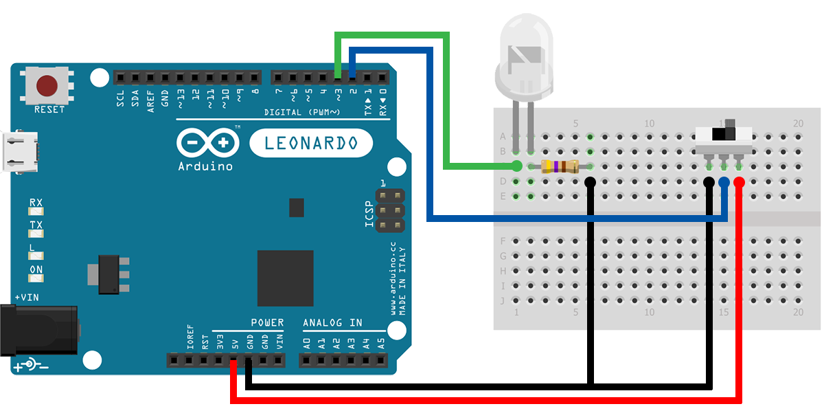
Let's now see an example. We'll use a SPDT (slide) switch. The Arduino will read the state of the switch, and accordingly allow the LED to blink or not.
Make the following connections. The pole of the switch goes to pin 2 (input). Pin 3 (output) goes to the LED. When the switch is on the right position, pin 2 reads HIGH and the LED blinks. When the switch is on the left position, pin 2 reads LOW and the LED stops blinking.
Pay attention to how the code handles the blinking process. If we use the delay() function, the Arduino halts and won't be able to respond immediately to switch transitions. So, instead of using delay() and making the Arduino wait, we use the millis() function to check the time passed ourselves and do other stuff in the meanwhile.
Push Buttons
Push buttons are another type of switches. They are SPST switches, but there is one thing special about them. They have a specific relaxed (normal) state. That is, when a push button is not pressed, its contacts can be either open or closed. A push button, with its contacts open when not pressed, is called Normally Open (NO). A push button, with its contacts closed when not pressed, is called Normally Closed (NC).
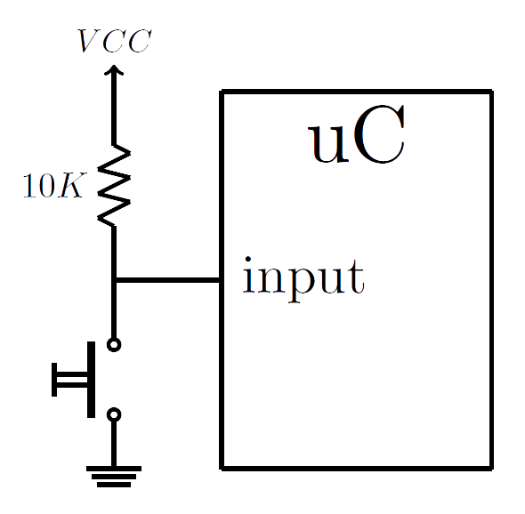
We've talked before about switches, back in Lesson 1 on Digital Inputs. We saw there that when a switch (a push button in our case) is open, we can experience strange readings when trying to read from an input pin. That's why we had to pull that pin to a voltage reference to drive it to a known state. If you need a refresher, go back to Lesson 1 and read the section about Pull-Up and Pull-Down Resistors.

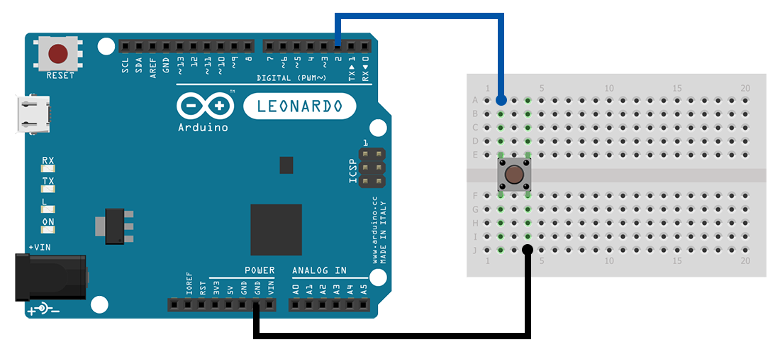
Push buttons, suited for breadboards, have a very specific form. As we can see in the figure, they have 4 leads. Any two opposite leads are always connected, and any two nearby leads get connected only when the button is pressed.
Let's now build an example and see how well a push button operates. We'll use a push button to toggle the state of the Arduino's onboard LED. This LED is connected to pin 13.
Make the following connections. Don't be alarmed that you don't see a pull-up resistor. We'll use the pin's internal pull-up resistor!
Upload the example to your Arduino, and pay attention to the LED as you press the button. Does the LED really changes its state every single time?
Debouncing
If you run the previous example, then you most probably noticed that although you were pressing the push button, sometimes the LED wouldn't toggle its state. This is due to a phenomenon called Switch Bouncing. When a switch's mechanism moves from one position to another, it doesn't do so instantaneously. It takes some time for the mechanism to settle to its new position. In the meantime, the mechanism performs some oscillations such that if we try to read the switch's state at that time, the result will be random. So, if an Arduino attempts to read continuously from its button pin within that transient period, it will perceive the event as multiple button presses.
There several ways to debounce a switch, both in hardware and software. Debouncing a switch in hardware involves employing an extra circuit to get rid of the oscillations and receive a straight, and clean, HIGH to LOW, or LOW to HIGH, transition. It has the benefit that the process doesn't occupy the microcontroller, but it requires additional components. The other approach is debouncing the switch in software. It involves delaying the acceptance of the button press until the transient period has passed so as to be sure that there has been indeed a button press, and the variation is not just some random event.
We will examine a software approach. It's a simple process that says we are going to take two measurements, one in the beginning of the signal transition, and one after the transient period has passed. Then, if those two values agree, we'll be accepting the button press, otherwise we won't. Also, we have to consider that not all switches have the same transient responses and periods. So, remember that in your own projects, you'll have to adjust for that fact (do some tryouts and figure out what is the bulk transient period of your own switches).
The circuit is the same as in the previous section. We'll use a push button in a pull-up configuration to toggle the state of the onboard LED. Only now, the difference is that the button presses will be successful.
Conclusion
Of course there many other types of mechanical switches out there, but nothing changes about how they operate. You have already the information you need to start including them in any of your projects.
The Schematics were based on fritzing.
Images are CC BY-NC-SA 3.0.